FAQ’s
FAQ’s
DXTMagnetics.com FAQ Questions
1. WHAT ARE FERRITE CORES? HOW ARE THESE CORES USED?
Ferrites are ceramic, homogeneous materials composed of various oxides with iron oxide as their main constituent. Depending on the application, there are two types of ferrite core material. Manganese-Zinc ferrite (MnZn) is used in applications requiring higher permeability and saturation levels. These power materials are generally used for high frequency transformer applications – important characteristics being high flux density and/or low core losses. Nickel-Zinc ferrite (NiZn) is used in applications needing higher resistivity and is more suitable for frequencies above 1 MHz. Applications are EMC, filtering, power, wireless transfer of power, etc. Cores can also be classified by shape: Toroidal cores, U core, E cores, I cores, Pot cores, cylindrical cores, etc. Core geometries can be modified by machining to meet specific magnetic and mechanical requirements. Core gapping, Toroidal slotting and custom machining available.
2. WHAT IS THE DIFFERENCE BETWEEN NICKEL-ZINC AND MANGANESE-ZINC FERRITES?
MnZn materials have a high permeability, while NiZn ferrites have a low permeability. Manganese-zinc ferrites are used in applications where the operating frequency is less than 5 MHz. Nickel-zinc ferrites have a higher resistivity and are used at frequencies from 2 MHz to several hundred megahertz. The exception is common mode inductors where the impedance of MnZn material makes it the best choice up to 70 MHz and NiZn is recommended from 70 MHz to several hundred GHz.
3. WHY ARE THERE DIFFERENT SHAPES OF FERRITE CORES?
Ferrite transformer cores are made in a variety of different shapes. Each shape has optimum proportions to obtain specific desired characteristics. For example, the pot core is designed for a high degree of magnetic shielding, while ER cores are designed for their low profile. Even with this optimization, it must be remembered that practical considerations must be met. Typically, the termination requirement, land pattern, EMI concerns, and profile height all lead to the proper choice of core shape. The geometric arrangement of the terminals must usually be compatible with the printed circuit grid or land pattern. These considerations lead to the use of a specific coil former having a specified number of terminal pins or pads arranged in a particular pattern. The core selection must often be designed around the termination requirement. In today’s industry, height restrictions and EMI shielding are becoming an issue. Therefore, low profile designs and pot cores may need to be considered.
4. WHY ARE FERRITES AVAILABLE IN DIFFERENT MATERIALS?
Ferrite comes in a wide variety of material offerings to give optimum performance (typically lowest loss) at varying temperatures and/or frequencies. For example, Ferroxcube 3C95 material is designed to give flat loss between 25-100C, while 3C98 is designed for minimum losses at 100C. Another example Ferroxcube 3F3 material is designed for optimal frequency <400kHz while 3F36 is designed for <600kHz. The first questions asked when inquiring about materials is what temperature and what frequency will you be operating at.
5. WHAT ARE AMORPHOUS AND NANOCRYSTALLINE CORES? HOW ARE THESE CORES USED?
Amorphous metals are produced by using a rapid solidification technology where molten metal is cast into thin solid ribbons by cooling at a rate of one million degrees C/sec. Amorphous magnetic metal has high permeability due to no crystalline magnetic anisotropy allowing smaller, lighter and more energy efficient designs in many high frequency applications for inverters, adjustable speed drives and power supplies. Due to the material having no crystalline magnetic anisotropy, amorphous magnetic metal has high permeability which makes it an ideal option for applications in the alternative energy sector. Amorphous iron (Metglas®) and nanocrystalline (FINEMET®) work well in mag amp and high efficient power applications while amorphous cobalt (Toshiba) works well in suppression devices.
6. WHAT PARTS ARE TYPICALLY NEEDED TO BUILD A COMPLETE ELECTRONIC TRANSFORMER?
There are many different types of transformers available, so our description will be very general. Typically, all transformers consist of windings and a core, so they will need magnet wire and a core material such as ferrite, powder cores or amorphous. Other materials that are typically seen in transformers are bobbins (engineered plastic to precisely hold the wire), insulation (tapes and paper to keep the wires in place and electrically separated from each other) and clamps (to keep core halves together).
7. WHAT IS A GAPPED CORE? WHEN IS A GAPPED CORE NEEDED?
A gapped core is when one leg (typically the center leg) has a small section removed. Introducing an air gap into a core, “tilts” or “shears” the B-H loop, making it possible to use the core at higher H levels. It is desirable, for many applications such as inductors, to delay this saturation. Air gaps have an added advantage in allowing for tighter control on inductance.
Depending on the size of the gap, it will vary the AL of the core. A gap can be specified in one of two ways, either by the dimension or the electrical AL value.
8. WHAT CRITERIA NEED TO BE DEFINED WHEN ORDERING A GAPPED CORE TO AN AL VALUE?
Ordering a gapped core to an AL value implies that a core will be gapped and measured using a decade bobbin (10, 100 or 1000 turns) in a non saturating region of the BH curve. Cores can also be gapped to an inductance value with different than decade turns, however both the number of turns and inductance should be specified. For best results, provide a test bobbin that will represent what is needed in production.
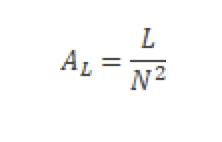
9. WHAT IS AL VALUE?
AL value or inductance factor (also known as inductance per turn and inductance per square turn) is a characteristic for a given magnetic core provided by the manufacturer.
AL has the unit henry (H), but the relationship to inductance is non-linear and the practical unit is nanohenry per square turn or nH/turn 2. It should be noted that the AL value is often given in the units of (nH) or similar, with the “per square turn” implied AL is defined as:
10. WHAT IS CORE SLOTTING? WHEN IS IT USED
Slotting is a bit different than gapping. A slot is used in toroids, placing a gap in the magnetic path. This is typically used in Hall Effect devices for current sensing.
11. DOES YOUR PROJECT REQUIRE DESIGN ASSISTANCE?
DXT provides design assistance on core material options, shapes, sizes and customization, as well as design services for transformers and inductors.
12. WHAT IS A POWDERED CORE?
Powder Core products are distributed air gap cores primarily used in power inductor applications, specifically in switched-mode power supply (SMPS) output filters, also known as DC inductors. Other power applications include differential inductors, boost inductors, buck inductors and flyback transformers. Characteristics of Powder Core materials are high resistivity, low hysteresis and eddy current losses and excellent inductance stability under both DC and AC conditions. In addition, Powder Core materials are not pressed with an organic binder, therefore, there is no thermal aging.
13. WHAT IS AN MPP CORE?
A Molypermalloy Powder (MPP) core is a toroidal magnetic core comprised from the powder of multiple alloys. It is distributed with air gaps to help condense its magnetic field to minimize core losses. Its composition is made from approximately 79% nickel, 17% iron, and 4% molybdenum.
14. WHAT IS A KOOL MU CORE?
Kool Mµ material is a low loss and relatively high saturation level (10,500 gauss) material. It is used extensively in power factor correction circuits (PFC) as well as unidirectional drive applications such as Pulse Transformers and Flyback Transformers. The near zero magnetostriction makes Kool Mµ (sendust) ideal for eliminating audible frequency noise in In-Line Noise Filters and Inductors.
15. WHAT IS AN XFLUX CORE?
XFlux cores offer an economical high saturation (1.6 Tesla) solution for use in low and medium frequency inductors and chokes. The high saturation is advantageous in applications where inductance under load is critical such as inverters for alternative energy, Power Factor Correction (PFC) boost , and Uninterruptible Power Supplies (UPS).
16. WHAT IS A HIGH FLUX CORE?
High Flux cores offer the highest biasing capability of all powder core materials. The high saturation flux density (15,000 gauss) and relatively low losses of High Flux cores make them quite useful for applications involving high power, high DC bias, or high AC bias at high power frequencies such as Switching Regulator Inductors, In-Line Noise Filters, Flyback Transformers, Power Factor Correction (PFC) , and Pulse Transformers.
17. WHAT ARE SINGLE, DOUBLE OR TRIPLE STACK BOBBINS?
With circuit board real estate becoming more expensive and the need for more power requiring larger cores, Dexter and Miles Platts developed multi-stack bobbins, allowing 1, 2 or 3 cores to be stacked on top of each other to allow a larger cross sectional area using the same board space.
18. WHY WOULD I USE A BOBBIN?
Electrical transformers, inductors and relay coils use bobbins as permanent container for the wire to form and retain shape, and to ease assembly of the windings into or onto the magnetic core. The bobbin may be made of thermoplastic or thermosetting (for example, phenolic) materials. This plastic often has to have a TÜV, UL or other regulatory agency flammability rating for safety reasons.
19. CAN DXT FABRICATE FROM A BLOCK OF FERRITE MATERIAL?
DXT stocks various blocks in multiple grades to allow quick machining of product. DXT is able to CNC and grind into unique shapes, allowing proof of concept prior to tooling a ferrite for pressing.
20. CAN I ORDER CUSTOM MATERIALS?
The materials that DXT provides are industry standard ferrite and powder core grades. DXT can also work on finding the correct material for an application, but cannot provide a custom grade of material.
21. WHAT ARE THERMISTORS? HOW ARE THEY USED?
A thermistor is a resistance thermometer, or a resistor whose resistance is dependent on temperature. … There are two types of thermistors: Negative Temperature Coefficient (NTC) and Positive Temperature Coefficient (PTC). With an NTC thermistor, when the temperature increases, resistance decreases.
22. WHAT ARE SOFT MAGNETIC CORES?
Magnetic materials can be divided into two classifications: soft and hard (sometimes called permanent). Permanent magnets are considered “hard” magnetic materials because their magnetism is permanently retained, a result that has been achieved by their manufacturing process. Cores are considered “soft” magnetic materials because they are magnetically biased only when wound with current-carrying wire. Hard magnets are fixed at one point on the B-H (or hysteresis) curve. Soft magnetic materials can be cyclically driven along portions of their B-H curves, making them usable for transformers and inductors. Magnetics ® manufactures soft magnetic cores which are used in a variety of electronic applications.
23. WHAT HAPPENS TO A CORE IF YOU GO ABOVE THE CURIE TEMPERATURE ?
Curie temperature is the temperature at which a material loses all of its magnetic properties. Beyond the Curie temperature, the core loses all useful properties in a circuit. Many cores have an insulated coating which would be ruined long before the Curie temperature is reached. In general, the core’s magnetic properties will be restored when the temperature is reduced to below the Curie temperature, as long as the material has not been oxidized or held at high temperature for extended period of times.
24. CAN I GET TIGHTER DIMENSIONAL TOLERANCES ON FERRITE CORES?
For standard pressed cores, this can be difficult. D uring the sintering operation, ferrite parts shrink to their final dimensions. Different material and processing techniques result in variance in this linear shrinkage which can range from 10 to 20% of the pressed dimensions. The resulting variation in fired dimensions results in final tolerances in the range of 1-4%. Some dimensions cannot be held to a tighter tolerance.
Dimensions that can be machined after firing can certainly be held to tighter tolerances. Parts machined completely out of blocks can also be held to a tighter tolerance.
25. CAN YOU TIGHTEN ELECTRICAL TOLERANCES ON TOROIDAL CORES?
While a production batch of toroids may have a wide tolerance, the cores can be graded into narrower inductance bands. Due to the equipment limitations, this is not possible on all sizes and permeabilities
26. WHAT ARE THE DIFFERENCES BETWEEN USING A DISTRIBUTED GAP (POWDER CORE) VERSUS A DISCRETE GAP (FERRITE)?
A distributed gap material such as Kool Mµ has each alloy grain insulated from the others. This allows for soft saturation over increasing current, giving inherent fault protection. Discrete gap cores hold high inductance out to a knee in the curve resulting in sharp saturation. Distributed gap cores hold better B and DC bias at high temperatures. Discrete gap cores have fringing flux around the gap adding significantly to the losses.
27. WHAT IS THE MAXIMUM FREQUENCY AT WHICH YOU CAN OPERATE A MAGNETIC MATERIAL?
Primarily, this depends on the type of material. Strip wound cores generally will have a maximum usable frequency lower than ferrites, because the resistivity is lower, resulting in high eddy currents and higher core losses. The thinner the strip material, the higher the usable frequency. On the other hand, core losses depend on the operational flux density of the design; thus, by reducing the flux density, a higher operating frequency can be achieved. Often in power magnetics, it is not the saturation flux density (Bsat) of the material that limits the drive level, but rather the maximum tolerable losses at the specific operating frequency. Consult the Magnetics’ Design Manuals to see the relationships among core losses, frequency, and flux densities.
28. WHERE CAN I GET CORE STANDARDS?
The organization recognized for new and existing core standards is the International Electrotechnical Commission (IEC). Specifically the group TC-51 works with core specifications – www.iec.ch. In addition, the IMA Working Group (https://www.transformer-assn.org/ima-working-group) has specified standard dimensions and chip and crack guidelines. Finally, IEEE 393 defines testing standards for core materials.
29. WHY ARE AL TOLERANCES WIDE FOR FERRITES AND NARROW FOR POWDER CORES?
Ferrites are sensitive to chemistry and kiln conditions. Fired cores have wide inductance tolerances, but machining an air gap in the core provides a tighter AL. Process control in ferrite manufacturing results in inductance ranges ±20% to ±30% (without 100% selection), in the case of ungapped cores. Process control in powder core manufacturing results in inductance ranges of ±8% to ±15%.
30. WHY DO YOU PUT AN AIR GAP INTO CORES?
Introducing an air gap into a core, “tilts” or “shears” the B-H loop, making it possible to use the core at higher H levels. It is desirable, for many applications such as inductors, to delay this saturation. Air gaps have an added advantage in allowing for tighter control on inductance.
31. HOW DO I KNOW THE FERRITE HARDWARE WILL FIT ON THE CORE?
Cores are manufactured to standards that have been agreed to in the industry. Tolerances have been assigned to the critical dimensions. Generally, hardware fit should not be a problem. When possible hardware and cores should be purchased from the same source.
32. HOW ARE PROPERTIES AFFECTED WHEN CORES ARE STACKED?
Stacking cores will increase the cross section (A e ) by the multiple of the number of cores in the stack. The magnetic path length (l e) will remain constant. The A L can be estimated by the same method as for single sets, where a leakage adjustment is estimated based on the ratio of window area to core area. Because that ratio decreases as cores are stacked, the A L of n stacked sets are slightly less than n times the A L of a single set.
33. HOW DO YOU GLUE FERRITE CORES?
Gluing should be done with thermosetting epoxy resin adhesives. The available range is very large. Important factors in the choice are the required temperature and viscosity. The economic curing temperature must not be above the maximum temperature to which the assembly may be safely raised. High viscosity resin can be difficult to apply Low viscosity resin may run out of a poor fitted joint or may be absorbed by the porous ferrite material. Follow the manufacturer’s instructions for a particular resin. Take care not to thermal shock ferrites; raising or lowering the core temperature too rapidly is dangerous. Ferrites will crack if changes in temperature exceed 5-10°C/min. In addition, care must be taken to match the adhesives’ coefficient of thermal expansion (CTE) to that of the ferrite material. Otherwise, the resin may expand or contract more quickly than the ferrite; the result can be cracks that will degrade core properties.
34. WHAT IS THE PROPER CLAMPING PRESSURE FOR FERRITES?
Generally, a recommended figure is about 700 kg/m2 (100 lbs/sq. in.) of mating surface.
35. WHY DO YOU FLAT-GRIND FERRITE CORES?
Cores are flat-ground on the mating surface because of the uneven surface produced during the firing process. It is important for cores to mate with a minimum air gap to keep the gap losses low and to achieve optimum inductance
36. WHY IS THE FERRITE GAPPED TOLERANCE NOT ALWAYS ±3%?
Due to limitations of the machine performing the gapping, as the gap dimension decreases it is increasingly difficult to hold tight tolerances. As A L increases, the gap gets smaller and the tolerances increase. As the gap gets smaller, the mechanical tolerance becomes proportionately larger, in addition the influence of variation in the material permeability becomes greater A gap specified by its A L value yields a tighter tolerance than a gap specified by its physical dimensions.